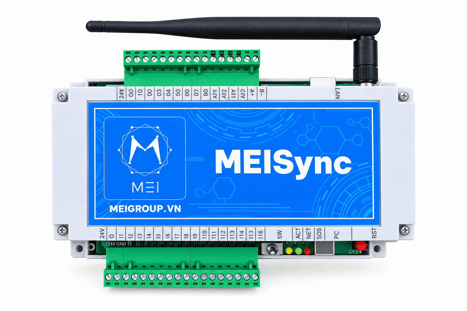
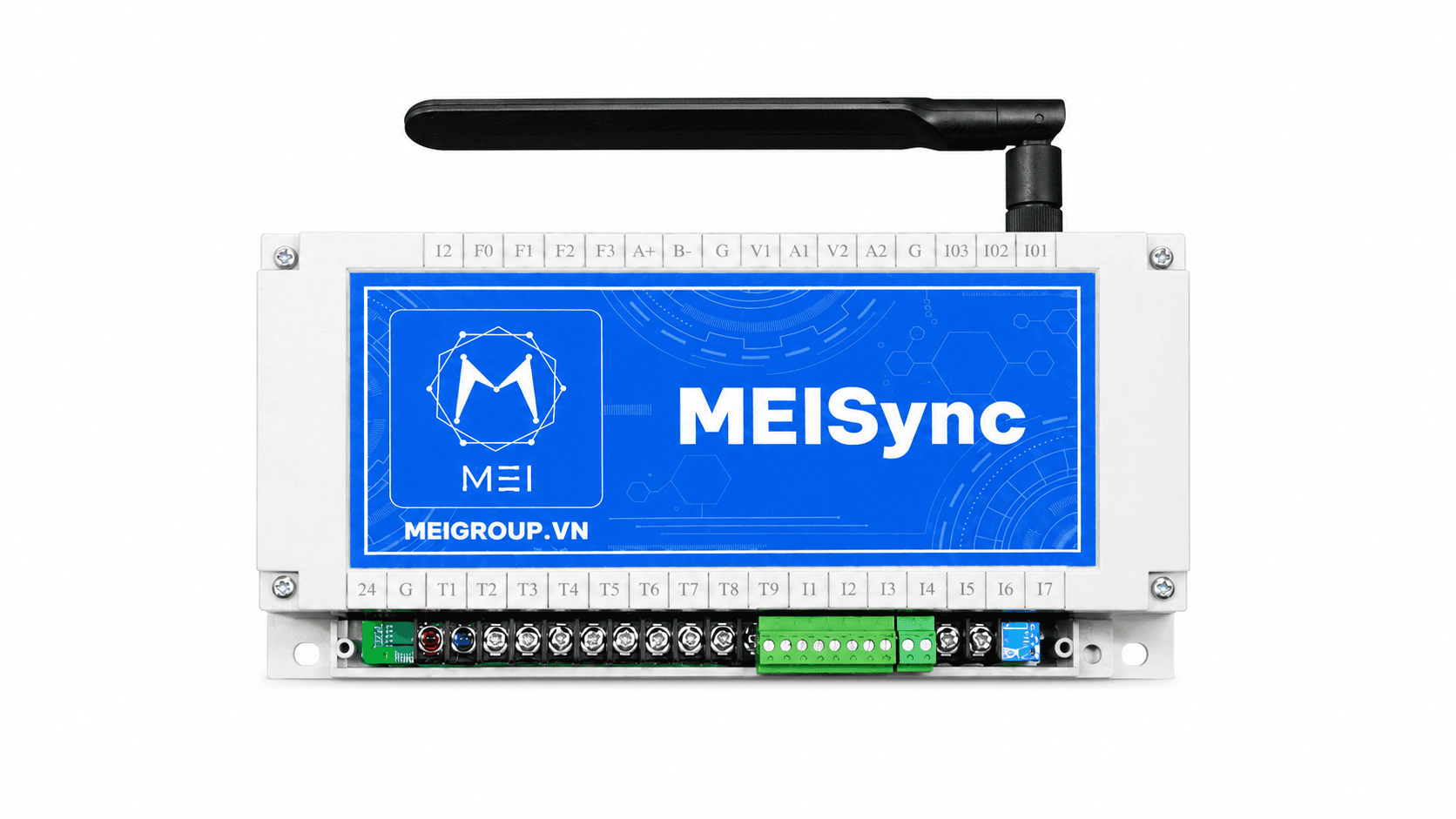
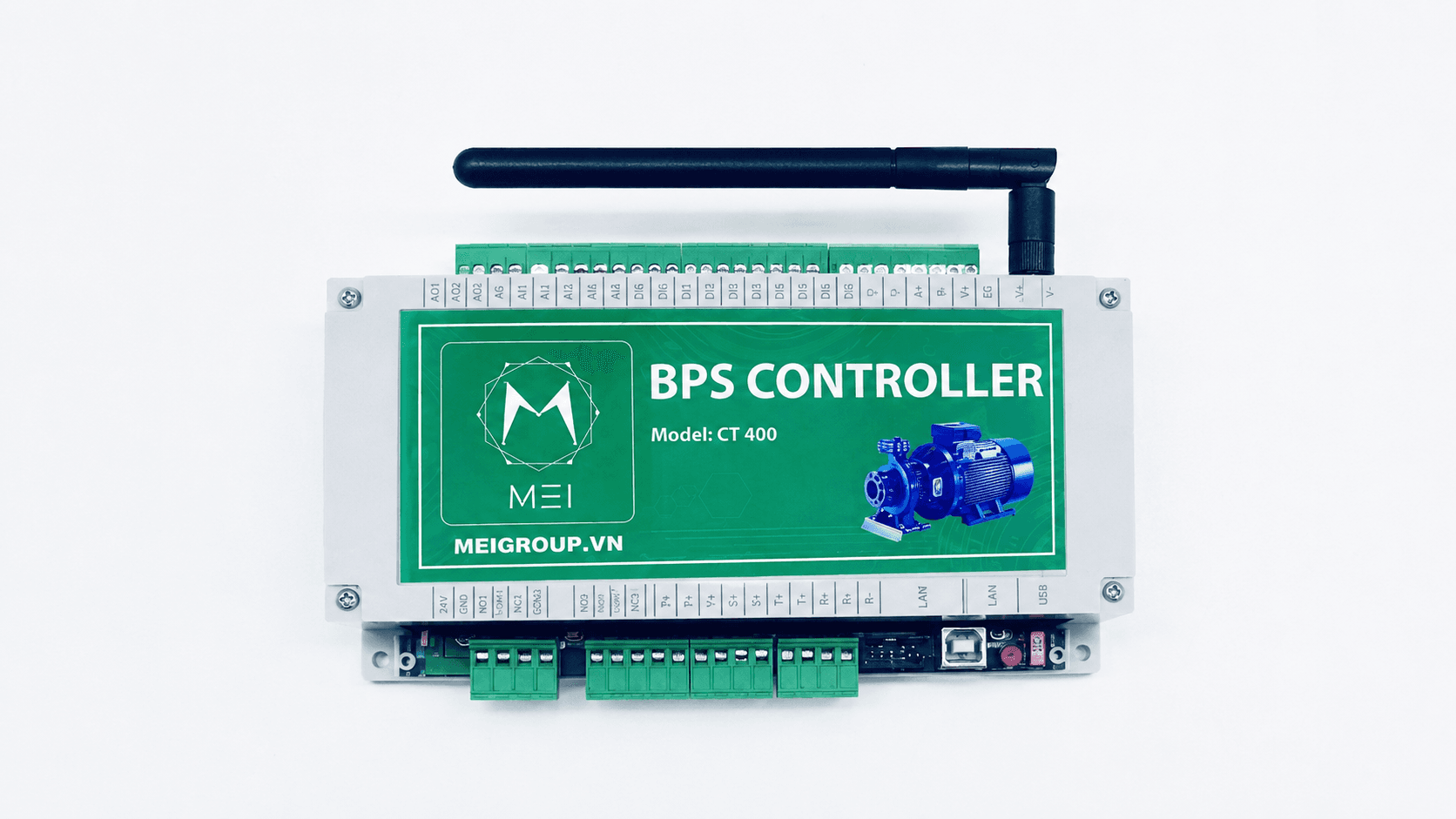
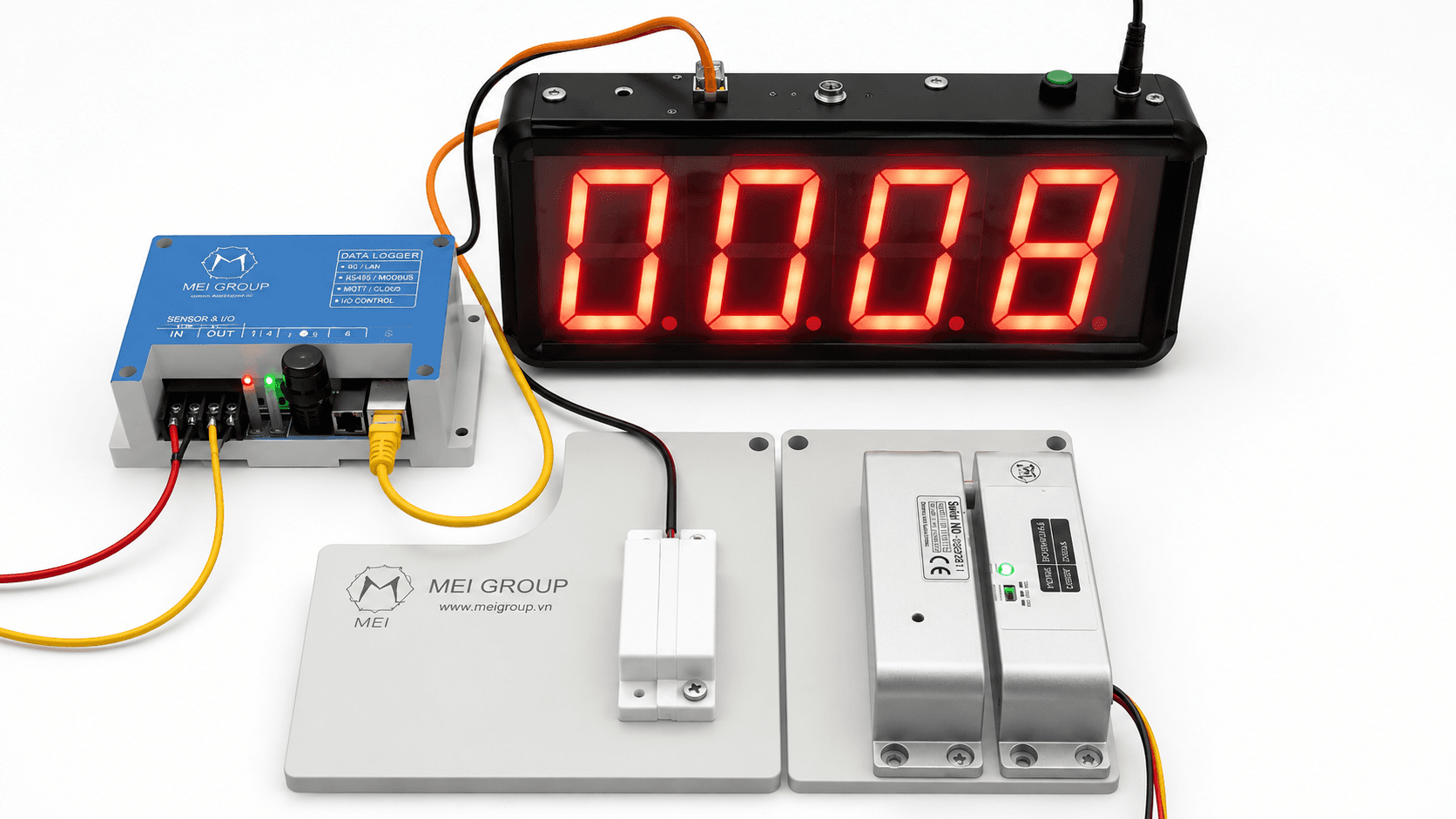
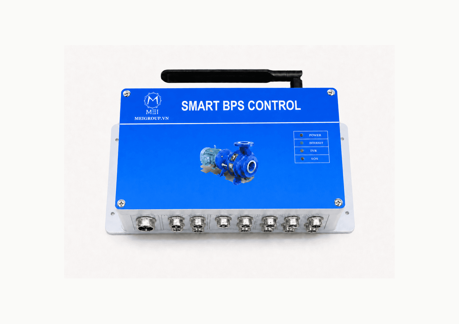
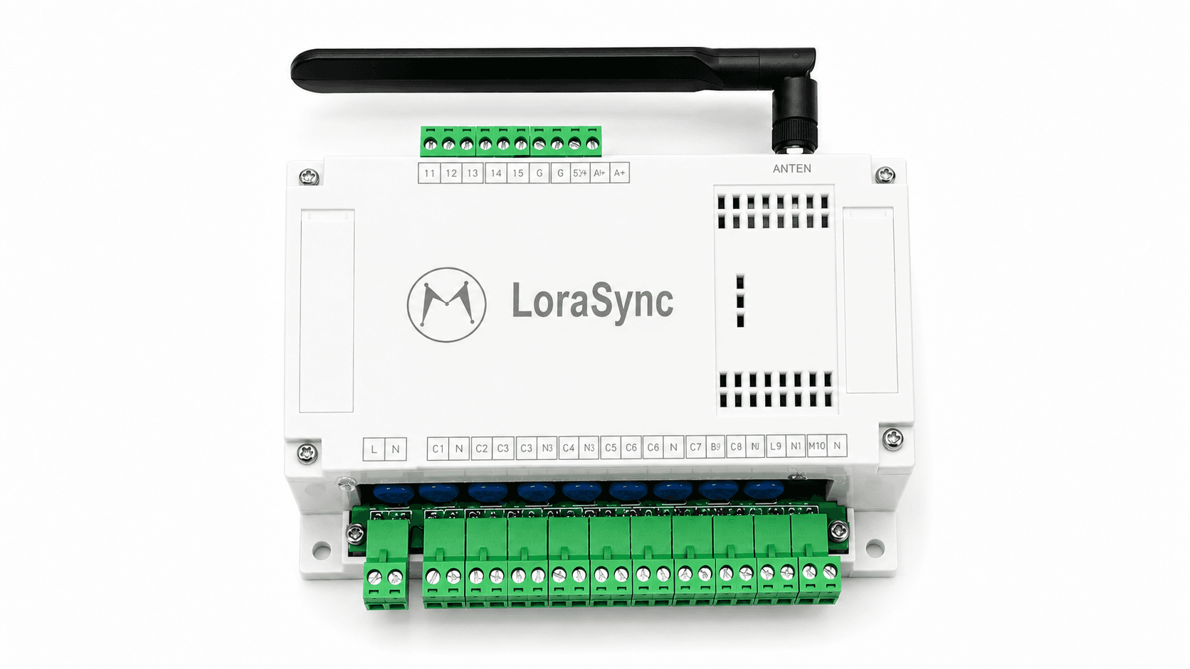
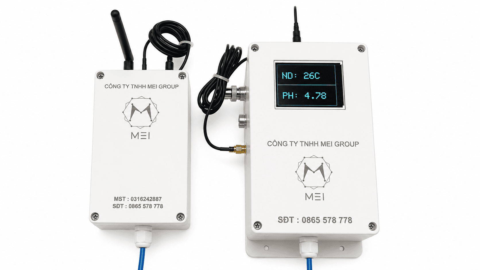
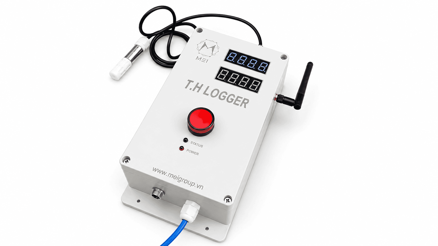
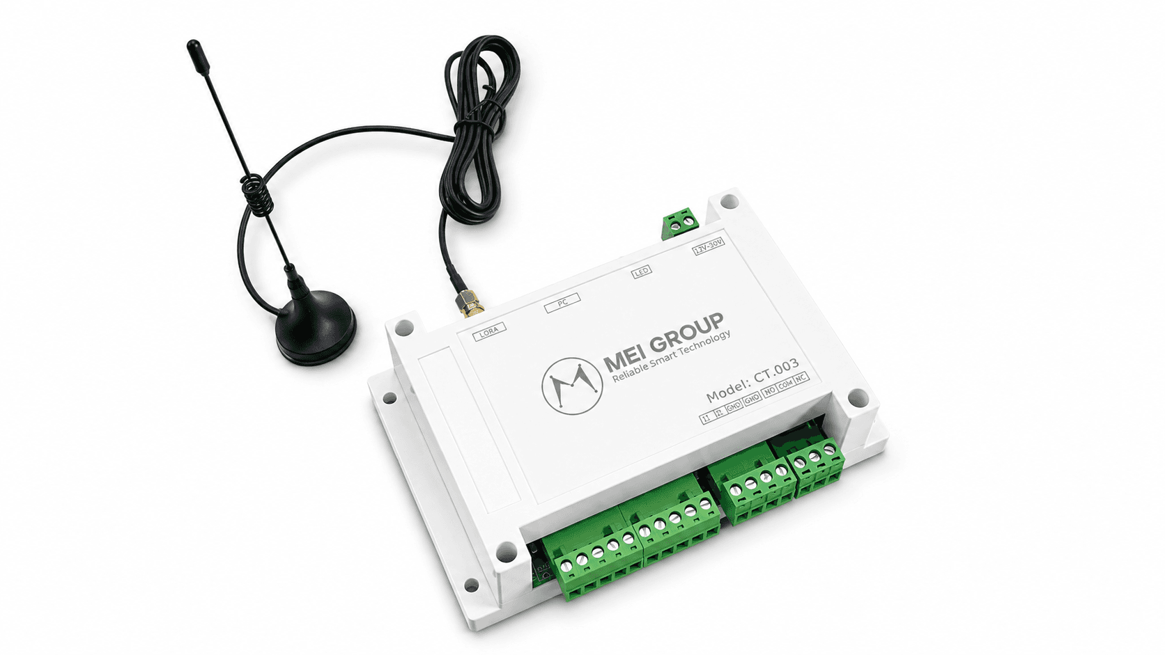
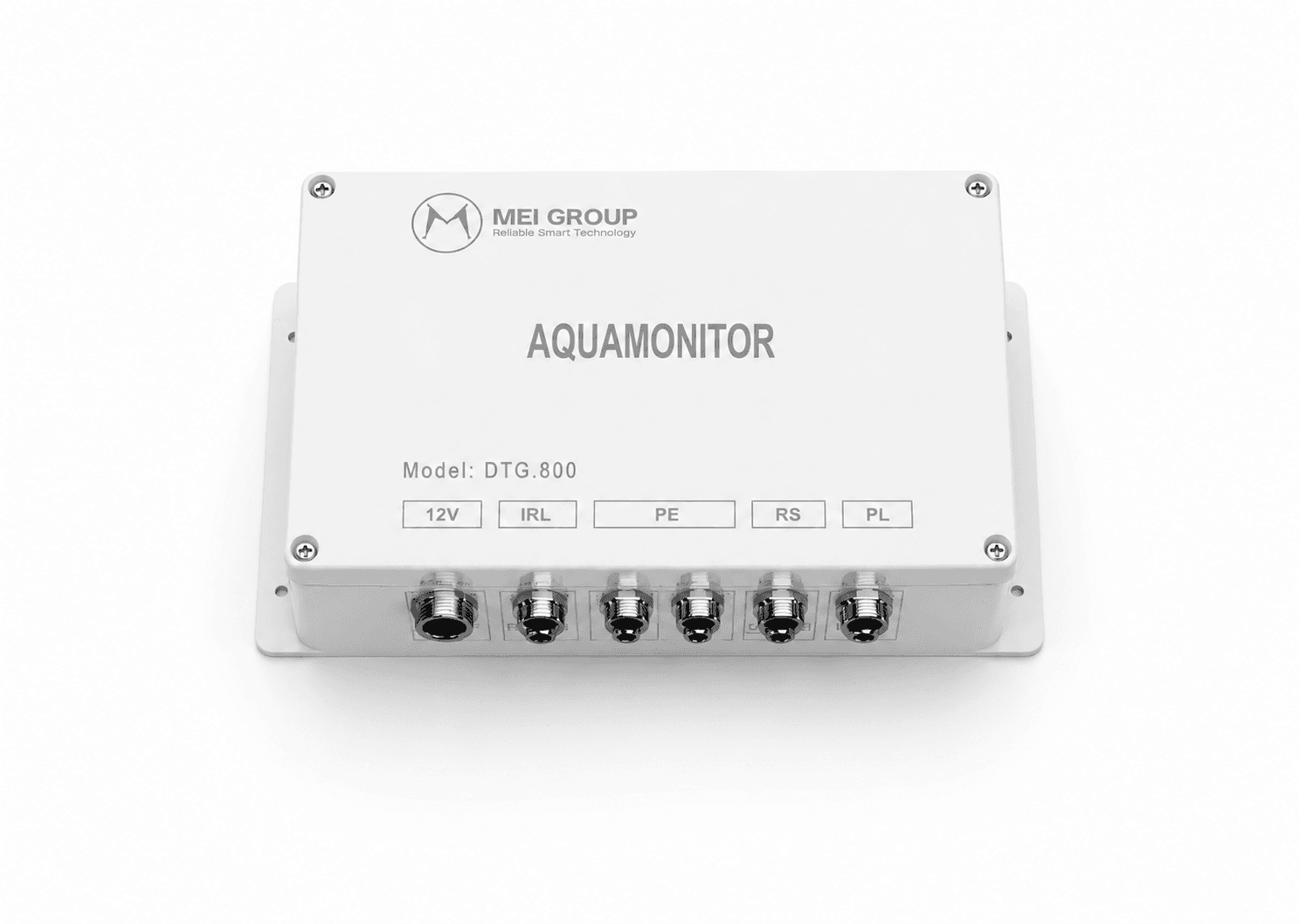
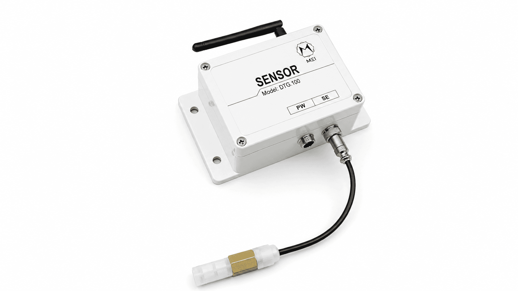
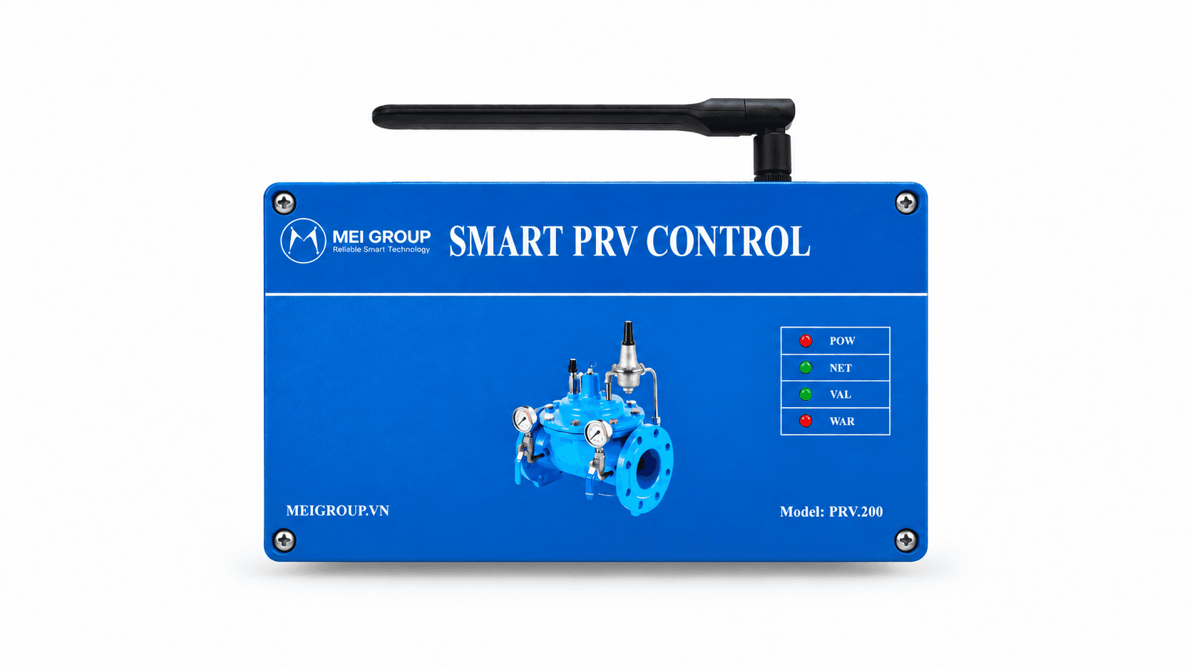
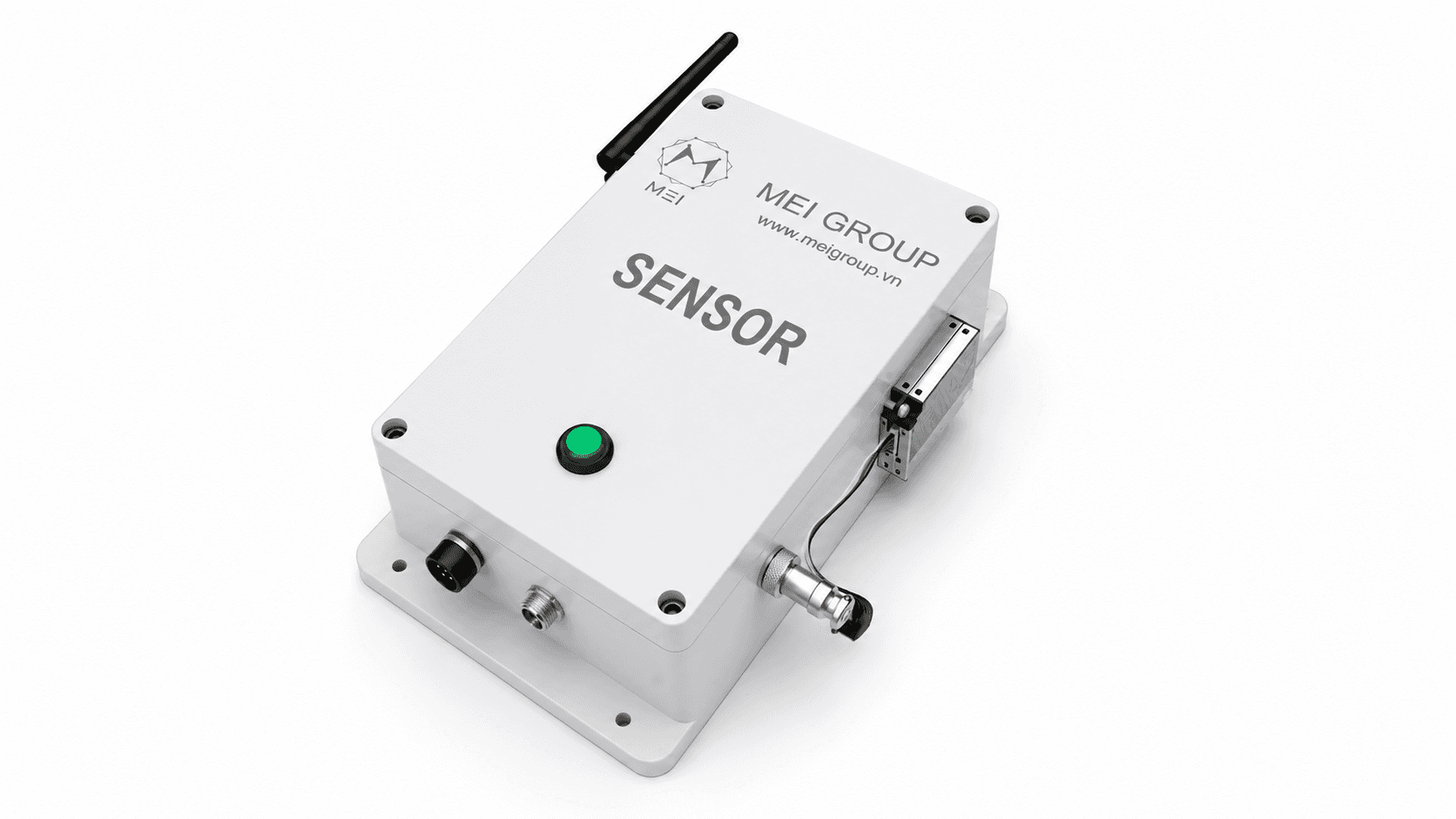
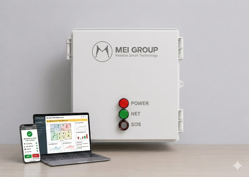
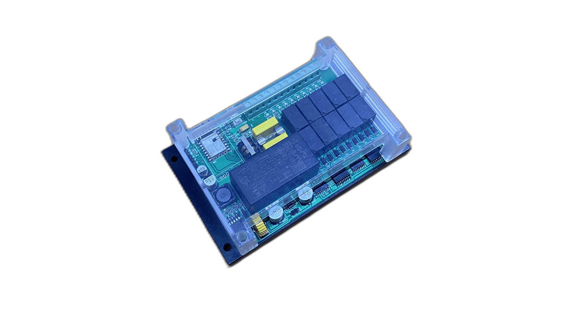
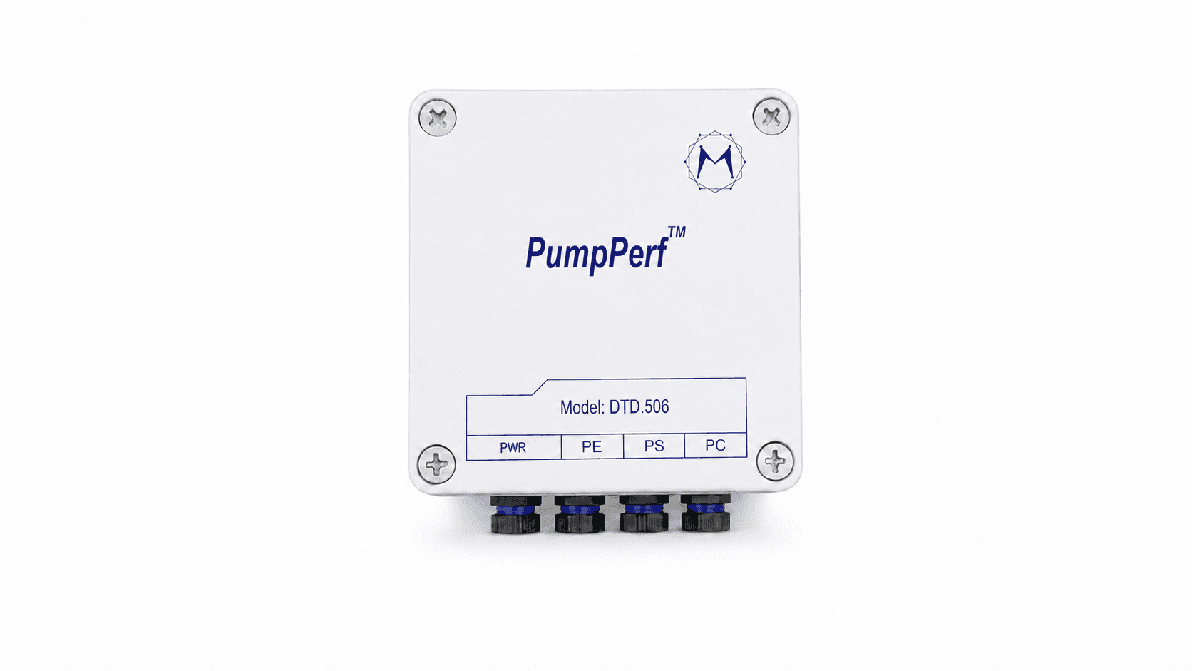
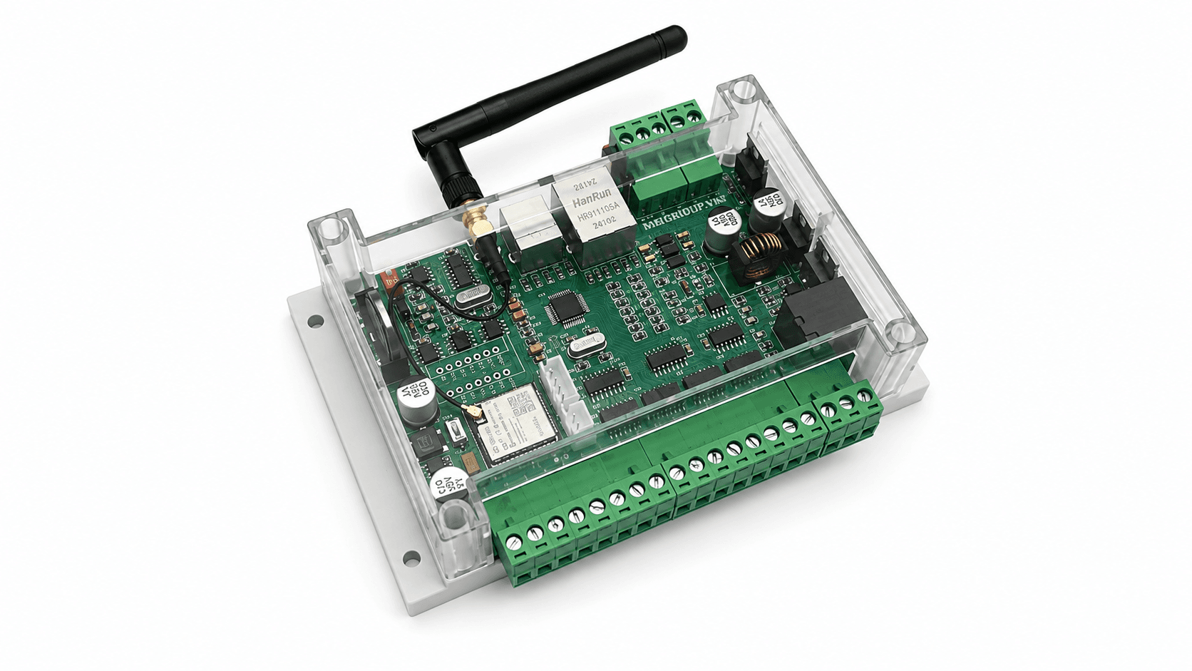
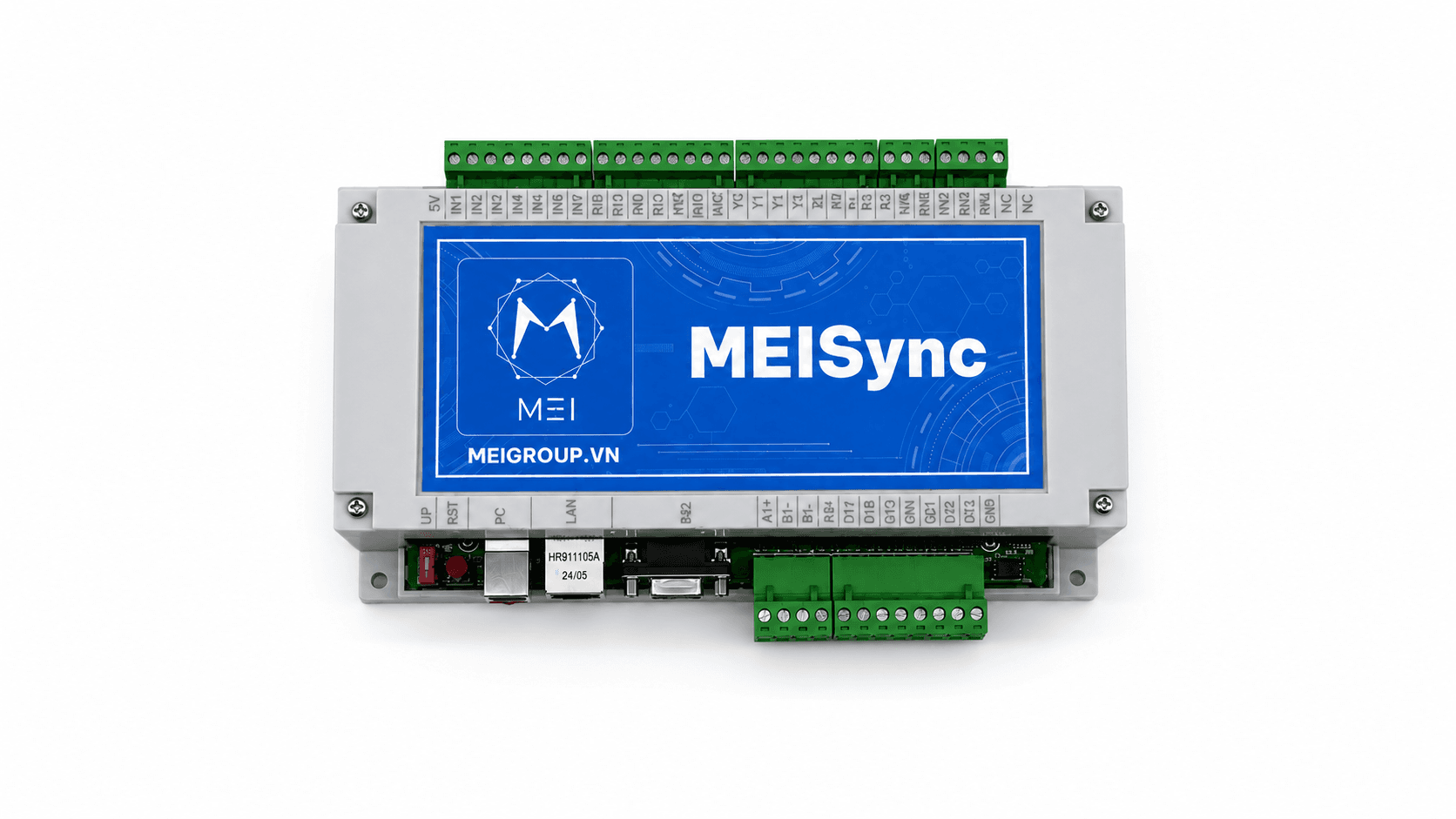
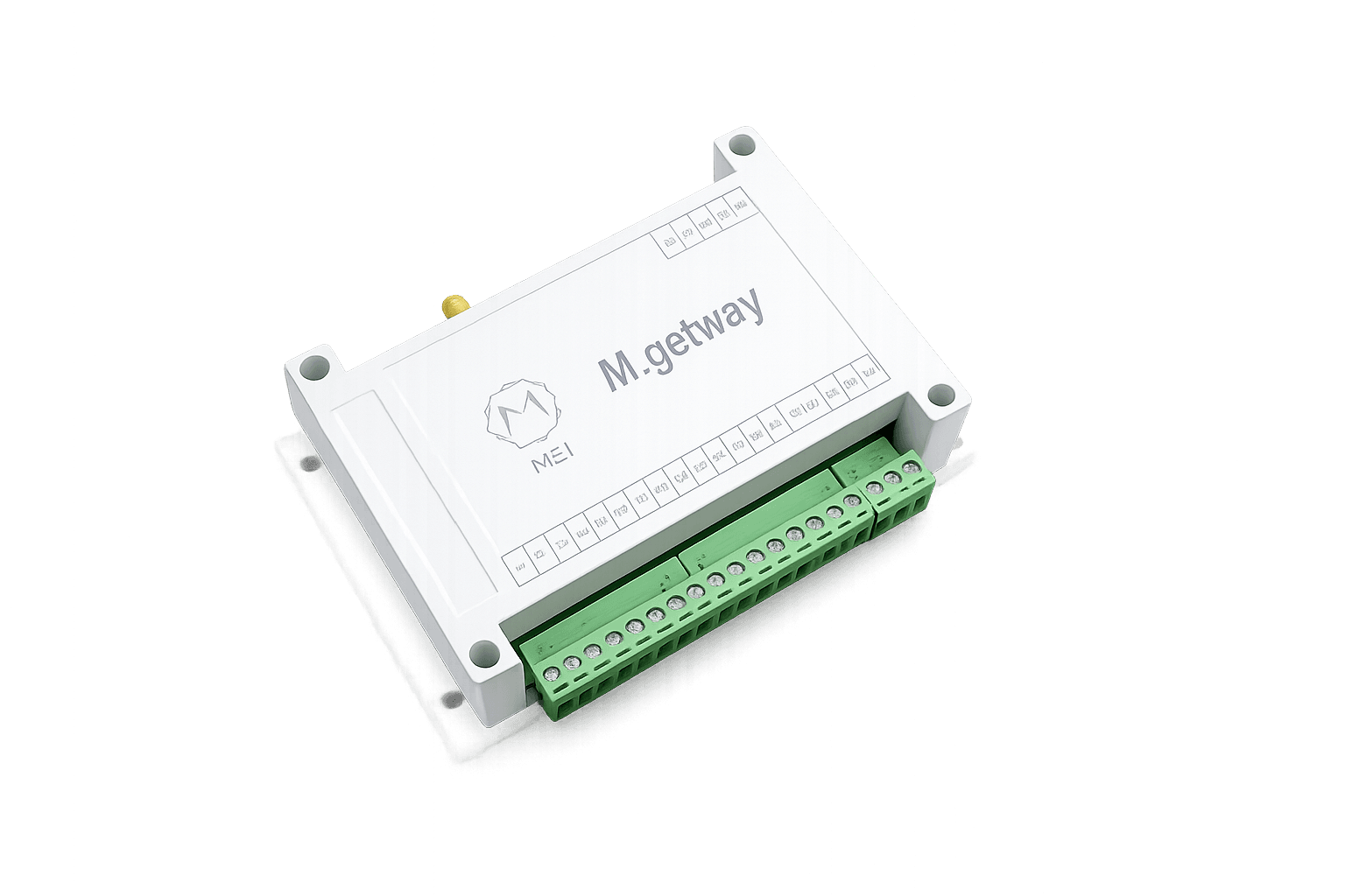
Level 1 pumping station monitoring and control equipment of MEI GROUP is a smart controller for raw water exploitation pumping stations, well pumping stations and upstream water supply systems. The device allows simultaneous control priming pump, submersible pump, drain pump following an automated process, ensuring safe and continuous operation.
The device collects data from well water level sensors, pressure sensors, flow sensors, motor temperature and electrical cabinet status. Based on this data, the system automatically controls priming pump to create input pressure and operate submersible pump according to the required water level and pressure, and activate at the same time drain pump when the sump water level exceeds the threshold or when there is an overflow incident.
The device supports many protection mechanisms such as: anti-dry running, overcurrent, pump stuck, low water, phase loss and automatically stops when there is an error. All data, warnings and operating history are synchronized MEI ECO, allowing 24/7 remote monitoring, error reporting via SMS/Zalo/Email, manual or automatic control according to scenario. Equipment suitable for level 1 pumping stations of cities, industrial parks and underground water exploitation systems.
MEI GROUP's level 1 pumping station monitoring and control equipment is a specialized industrial controller that manages the entire operating cycle. priming pump – submersible pump – drain pump in raw water exploitation systems or wells. The device is built on the industrial STM32/ESP32 microcontroller platform, supporting 24/7 operation with high safety protection mode.
1. Technical input - output signals
Well/tank water level sensor:
4–20mA, 0–10V, or PTC/PT100 sensor (depending on configuration)
Used to control priming and submersible pumps according to actual water level
Push head pressure sensor: 4–20mA, range 0–10 bar
Well or upstream flowmeter: pulse or Modbus RS485
Engine/pump temperature sensor
Digital Input: electrical cabinet status indicator, phase loss protection, ELCB, MCCB overload
Sump water level for drain pump (Low/High/High-High)
1.2 Output
Relay controls the priming pump, submersible pump, and drain pump (Start/Stop)
AO 0–10V/4–20mA to control the inverter if needed
DO warnings and alarms in place
RS485 Modbus Communicate with the inverter or central electrical cabinet
2. Automatic control process
2.1 Control of priming pump
Start the priming pump when the well water level reaches the threshold
Automatically stops when pressure is sufficient or after maximum priming time
Dry running protection – low water protection
2.2 Submersible pump control
2.3 Control the drainage pump
Start when the sump water level is high
Run alternately (alternately) between pumps to balance the load
Automatically stops when water level is low
3. Technical protection mechanisms
Prevents running dry for submersible and priming pumps
Overheat protection engine
Overcurrent – overvoltage – phase loss protection (from electrical cabinet or Modbus inverter)
Self-locking pump error, activate the backup pump
Low water level/out of water protection
Sump overflow protection, automatically starts the drain pump
4. Connect to the MEI ECO ecosystem
Devices connect to MEI ECO via:
Transmitted data includes:
Status of each pump (RUN/STOP/FAULT)
Well water level
Push head pressure
Pump flow
Engine temperature
Alarm history – pump running history
Total operating hours for each pump
Control support from MEI ECO:
5. Warnings & safety requirements
Warning system via SMS, Email, Zalo/Telegram, WebApp when:
The well is dry
Submersible pump error/overheating
The priming pump cannot create pressure within the allowed time
The drain pump does not operate when the sump is full
Lost connection to electrical cabinet
Power outage station – power restored
Full logging facility for incident tracing.